<< Back to Index

TECHNICAL ARTICLES

The six guidelines you need to specify a bulk bag filler

By David Boger
Vice President, Global Business Development & Marketing
Flexicon Corporation

Exponential growth in the use of bulk bags has spawned an entire manufacturing segment dedicated to producing specialized equipment that not only fills and discharges bulk bags, but offers various degrees of automation and integrates filling and unloading operations with upstream and downstream equipment. As the number of equipment options increases, so should the ability of the specifier to evaluate stand-alone equipment and integrated systems against current and anticipated needs. The author addresses the "filler" half of the bulk bag handling equation, offering the six most important parameters to consider when satisfying any individual bulk bag filling requirement with top efficiency and cost effectiveness.


1. Anticipate maximum capacity

The difficult but critical question: How many bulk bags will you need to fill per week during the useful life of your next bulk bag filler?

With few exceptions, buying a more costly filler with higher capacity than you now need will be less costly than replacing a filler you outgrow, unless that filler can be retrofitted with performance enhancements at a later date. Capacity requirements run the gamut, from one bag per week to 20 bags per hour. Where your volume falls should, in part, influence your decision to specify a manual, semi-automated or fully automated machine.

Generally speaking, the more manual the filling operation, the more output is subject to variation. When gauging the capacity and payback of manual equipment against automated equipment, you need to determine the average pace at which operators can attach, detach and cinch bag spouts, remove filled bags, load pallets and conduct all other filler-related operations. When estimating the time allocated to these manual functions, it is advisable to anticipate a pace that an operator can realistically maintain throughout an entire shift while avoiding fatigue or injury.

For the lowest volume applications, a basic filler operated manually will maximize your return on investment. One example is a medium-gauge TWIN-CENTERPOST™ filler (FIG. 1) which offers the structural integrity of four-post fillers but at significantly lower material and fabrication costs and with less weight. This two-post design also affords unobstructed access to the bag spout and loops, facilitating rapid manual insertion and removal of bags. This class of filler is typically equipped as standard with fill head height adjustment via fork truck to accommodate all popular bag sizes, a feed chute vent port for dust-free air displacement during filling, and an inflatable cuff to seal against the bag inlet spout and ensure it does not collapse on itself during filling.

FIG. 1


Limited performance options, which can be added initially or retrofitted, include an inflator to expand the bag prior to filling, and a programmable scale system with flow control valve for filling by weight.

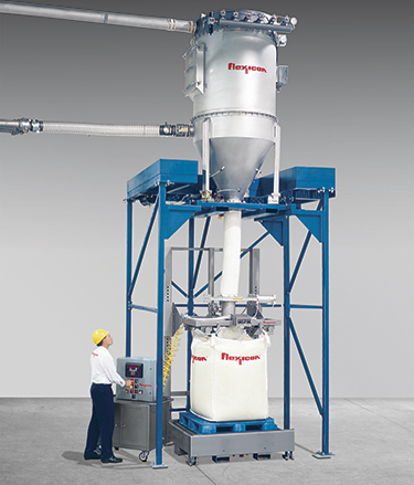
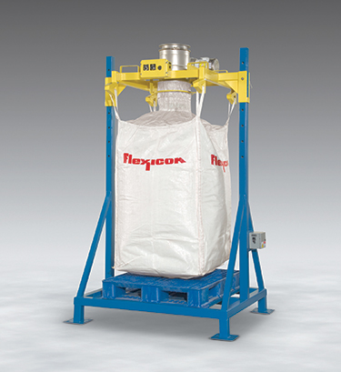
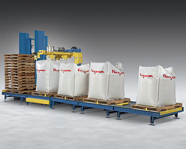
The cost of a scale system can be avoided by placing the entire filler onto an all-purpose plant scale, providing the filler is properly equipped for in-plant mobility (FIG.2).

FIG. 2


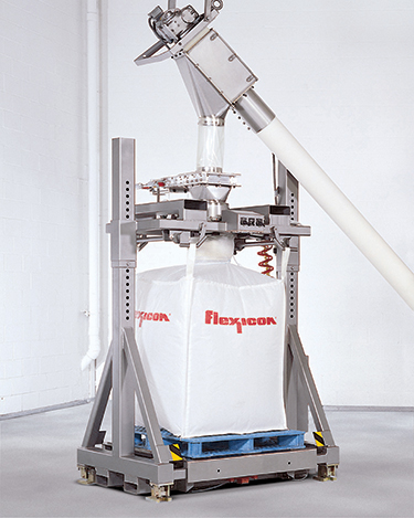
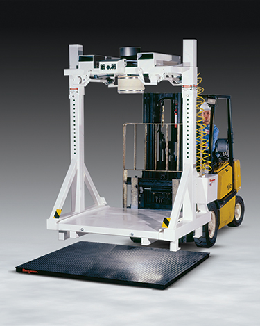
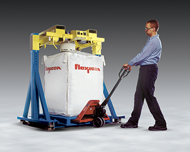
If a forklift is unavailable to remove filled bags, as is required by the above-mentioned fillers, configurations are available with a three-sided base that provides access from the open side using a pallet jack (FIG. 3). This low profile configuration can also be utilized to conserve height in low headroom applications.

FIG.3


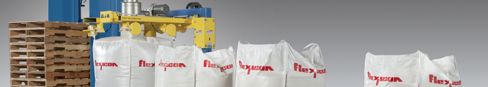
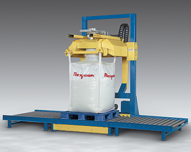
The time required to prepare empty bags for filling, and to remove filled bags from beneath the filler, can have as much or greater influence on maximum filling capacity than the rate at which material enters the bag. As such, adding a roller conveyor allows filled bags to be rolled out of the filling area for spout cinching and pallet/bag removal while another bag is being filled. Adding such a conveyor system, however, generally requires a filler with rear posts (FIG. 4) and a cantilevered fill head equipped with hooks that release bag loops automatically, so if higher capacity is in your future, a rear post configuration may be your best choice today.

FIG. 4


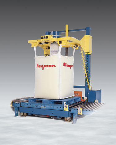
Increasing the capacity of systems equipped with roller conveyors to the next level generally entails adding an automated pallet dispenser (FIG. 5) which places pallets and slip sheets onto the roller conveyor upstream of the filling operation, further reducing the time required for each filling cycle by limiting manual operations within the filling station exclusively to loading an empty bag.


FIG. 5


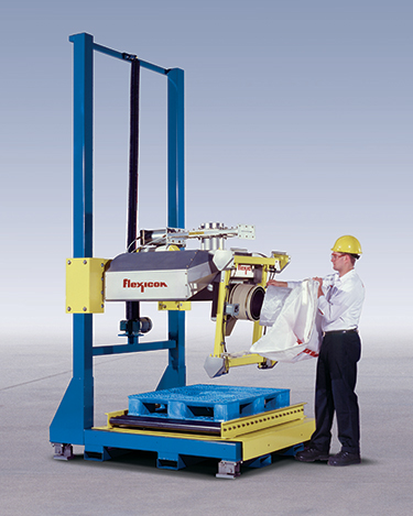
To further reduce the time needed to attach the spout of an empty bag to the filler, this SWING-DOWN® filler (FIG. 6) lowers the entire fill head to within an arm's length of an operator standing on the plant floor. Further, it pivots the bag spout into a vertical position, enabling the operator to connect the spout of an empty bag to the inflatable bag spout collar in several seconds, after which the spout pivots back to horizontal, the entire fill head returns to fill height, the bag is inflated, and filling commences. Additionally, when the bag reaches its target weight, the bulk material delivery system deactivates automatically, the spout collar deflates, the fill head raises to decouple from the spout, and the powered roller conveyor sends the bag downstream of the filling area — automatically, rapidly and safely.

2. Evaluate safety against manual operations required at any given level of capacity

With manual and semi-automated filling operations, the potential for worker fatigue and injury can increase according to required output per shift, relative to the type of bulk bag equipment specified.

Consider that the connection points of a conventional filler are often beyond the reach of most operators, even when short bags are being filled. But adding the height of a roller conveyor to the height of a bulk bag to the length of its bag loops puts the connection points for bulk bags of only 48 inches (122 cm) in height at approximately 7 feet (213 cm) above the floor!

This requires an operator to stand on a platform, a ladder or on the roller conveyor while straining to reach overhead spout connection points and inserting hands between temporarily disabled moving parts. Difficult-to-reach spout connection points can therefore compromise safety as well as capacity — two problems that can be solved with the addition of a fill head that lowers and pivots to the operator at floor level.

Repetitive manual tasks such as releasing bag hooks, placing pallets on a roller conveyor or actuating bulk material delivery, also increase the potential for error and injury, justifying semi- or fully automated equipment for all but the lowest volume applications.


3. Ensure dust is contained

Even the most rudimentary filler is likely to be equipped with an inflatable spout seal (FIG. 7) to hold the bag spout firmly in place during filling. However, not every fill head is vented to a dust collector to filter displaced air and dust, and to vacuum ambient dust in the operator's vicinity during disconnection and cinching. It is therefore important to confirm that the filler you are considering is so equipped, particularly when contamination of the product or plant environment cannot be tolerated.

4. Determine your need for multi-function filling

If your plant fills drums, boxes or other containers as well as bulk bags, multi-function fillers (FIG. 8) can boost production, undercut the cost of separate equipment and reduce the amount of floor space required. Multi-function fillers can be switched from bulk-bag to drum-filling mode in seconds by positioning the swing-arm-mounted drum-filling chute under the fill head discharge port. The chute automatically rotates to deliver material to all four drums on a pallet. Similar adapters for boxes, totes or other containers are also available with varying levels of automation.

5. Match the feed source to your material and your filler

Filling capacity, accuracy and efficiency are often limited by the ability of upstream equipment to feed material consistently and in sufficient volumes. High capacity, semi- or fully-automated fillers therefore require high-capacity feeding systems that are typically automated and feed material into the filler by gravity or by a metering device.

The ability to gravity-feed material depends on whether a material storage vessel can be located above the filler, and on the material's flow characteristics. The more free-flowing it is, the more accurately its flow can be varied (down to dribble-feed rate) by a slide gate or other valve that must close the instant a precise target weight has entered the bag. Non-free-flowing titanium dioxide (TiO2) for example, may flow in a trickle and then in clumps, and it may bridge above the flow control valve, making it a poor candidate for gravity feeding.

For non-free-flowing materials, a metered feeding system is required to feed the filler accurately and consistently. Metering systems can include a flexible screw conveyor (FIG. 9), screw feeder, rigid auger, drag disk, bucket elevator, rotary airlock valve, or other device that does not rely on gravity alone to deliver material to the filler.

FIG. 9


The selection of a metering system can hinge on the available space above the filler, since surge hoppers and filter receivers with rotary airlock valves may require more headroom than is available. In these cases the discharge housing of a flexible screw conveyor can often fit between the filler inlet and the ceiling joists, while eliminating the need for a flow-control valve.

For products that are easily aerated, pneumatic conveying systems should be avoided, since the conveying process can cause the material to require a much lengthier densification/deaeration cycle to achieve the desired fill weight and package stability.

If sufficient headroom exists above the filler, a surge capacity equivalent to the weight of a filled bag can be employed to reduce cycle times while maintaining accurate fill weights. This configuration allows bag change-over to occur while the subsequent batch is in the process of being weighed. When a pneumatic conveyor is used as the material delivery system, the filter receiver can be sized to hold the weight of an entire bulk bag (FIG. 10) to apply this method.

FIG. 10


For the same reason, a surge hopper above the filler can be considered when utilizing mechanical metering devices moving material to the filler from both storage vessels and plant processes.


6. Comply with sanitary requirements

While all fillers can be constructed of stainless steel with ground and polished welds, their designs can preclude sanitizing according to government standards. If your application must meet sanitary requirements, your choices should be limited to designs that are accepted by the USDA Dairy Grading Branch (FIG. 11) or other agencies to which you must comply, or to which you elect to comply for assurance that sanitary conditions can be maintained.

Conclusion

With an almost unlimited combination of filler designs, features and upstream equipment from which to choose, specifiers have the ability to tailor bulk bag filling systems according to capacity requirements, expandability, safety concerns, plant hygiene considerations, ancillary filling needs, upstream equipment and sanitary standards. While numerous available options can complicate the selection process, they can also yield a highly efficient and cost effective solution to any given filling problem, providing that fundamental steps are taken to evaluate equipment against precise requirements.

HAVE A FLEXICON ENGINEER CALL ABOUT YOUR APPLICATION > >

Z-0398